Designed and made in Montpellier by Dmitry KORZHENEVSKIY
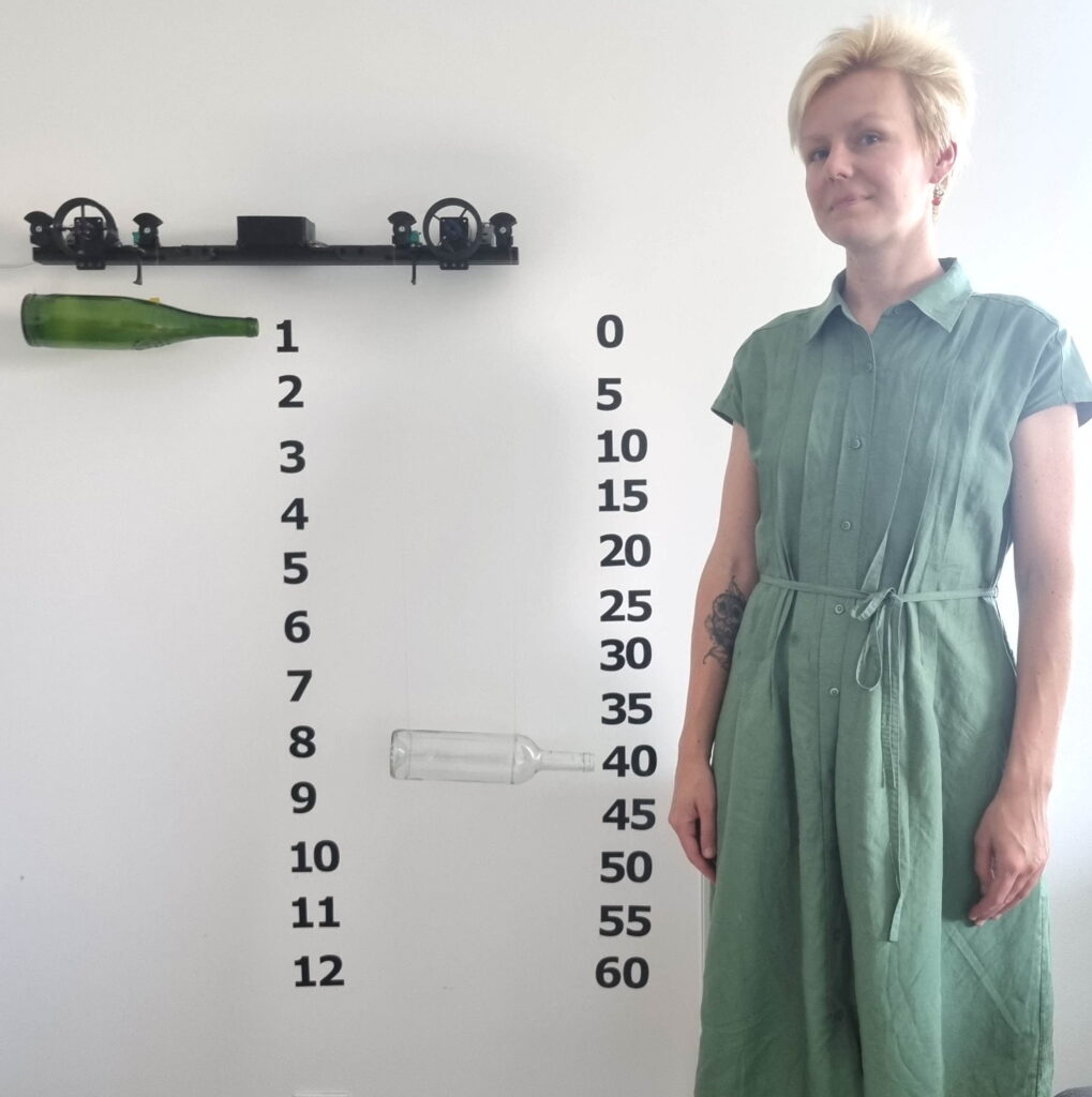
In an world where digital displays dominate, the charm of mechanical clocks still captivates many. My latest project combines the elegance of mechanical movement with modern technology to create a unique and functional clock. It uses a motorized system to raise and lower indicators on a string, pointing to the hours and minutes. Whether it’s a striking piece for your home or a conversation starter in the office, this clock is sure to catch the eye and spark curiosity.
I will take you through the journey of building this clock, detailing the software architecture, the electronics involved, and the mechanical engineering challenges I faced and overcame.
How does it work?
To explain it I want to separate it into 3 major chapters:
- Software
- Hardware (electronics)
- Hardware (mechanics)
Software
I have chosen ESP32 as a main processing unit. This is a chip that is pretty powerful, it has Wi-Fi, Bluetooth, 2 cores, plenty of inputs and outputs.
The task seem straightforward: maintaining time accuracy and operating the motors. One for hours and one for minutes.
Where does the time comes from? I wanted to develop this clock so it can work completely offline or with a internet connection or a combination of both.
To do that I developed 3 levels of timekeeping.
Level 1 (ESP32 timer)
This is internal clock that works on the ESP32 chip using its own oscillator. It is accurate enough for a period of couple of days. When it turns on it has no knowledge of real time.
The software that displays the time (sends commands to the motor) uses this time (not time from other levels).
Level 2 (DS3231MZ+)
This is external chip that sits on the board near the ESP32. It keeps real time with the help of lithium battery. If the whole device is switched off the time is not lost, the chip keeps counting.
The challenge with timekeeping is the frequency of oscillators that make a waveform for the timekeeping chip change with temperature.
What makes this component remarkable is its internal temperature compensation feature. It retains factory-calibrated temperature and frequency values for optimal precision.
The manufacturer claims the accuracy of ±0.432 Second/Day. It means that in absolute worst case it will be off by 2.5 minutes after 1 year of working. In reality it is better than that.
But 2.5 minutes of error in a year is still a lot. This is why I have third level.
Level 3 (Internet time)
The ESP32 can access the internet to sync the time with time servers. The same way as all computers and smartphones do.
The flow of time over the levels
The time is passed from level 3 to level 2 and from 2 to 1 like a waterfall.
Level 3 updates once a day via the internet. And at the same time the the level 2 DS3231 clock refreshes its time. If internet is not available for some reason – no problem. In this case level 2 is used.
Level 2 passes the time to level 1 once every minute.
Level 1 updates automatically every second by default ESP32 library.
In order for the whole system to work it need to be connected to the internet at least once. For the sake of accuracy it is better to let it connect to the internet at least once a year.
How does it know for how much to turn the coil?
The elevators in the buildings that move people around also have a coil of wire attached to the spinning motor. The motor have feedback of the position of the elevator. And also each floor has a sensor to know exactly where the elevator is.
I don’t want to have sensors all over the wall where numbers are. And I don’t need to have constant position feedback.
Instead the endstops are used. Endstop is a switch that clicks and makes a contact just like a button when something hits it. When the machine it turned on the computer has no idea where the indicators are (wine bottles). It turns on and slowly coil both up until they hit the endstops. And when they hit the computer knows that they are at the very top.
To display the time it must also know the distance in millimeters to the first number (1 for hours and zero for minutes) and the distance to the lowest number (12 for hours and 60 for minutes). Knowing that and the diameter of the coil it can easily calculate how many turns in must make in order to arrive at any given position. In needs to do the homing (homing means finding the home, hitting the endstops) only once per day. It does is at night when the time is 1 am because this is a closest position to the endstops. This way no one will notice when this is happening.
Multicore operation
The ESP32 has 2 CPU cores. When I was a boy the computer with 2 cores was a luxury found in most expensive Intel CPUs. And now I have 2 cores inside a microcontroller that costs 5 dollars. What a time to be alive )
The software needs to send commands to the motor drivers (thousands times per second). If for some reason this task is slowed by other function the movement will not be smooth.
The solution was to utilize one processor core to only drive the motors and do nothing else. The second core handles the rest (Wi-Fi, online time sync, temperature measurement, clock update, i2c bus, etc).
After I switched to multicore operation the movements became smoother.
Hardware (electronics)

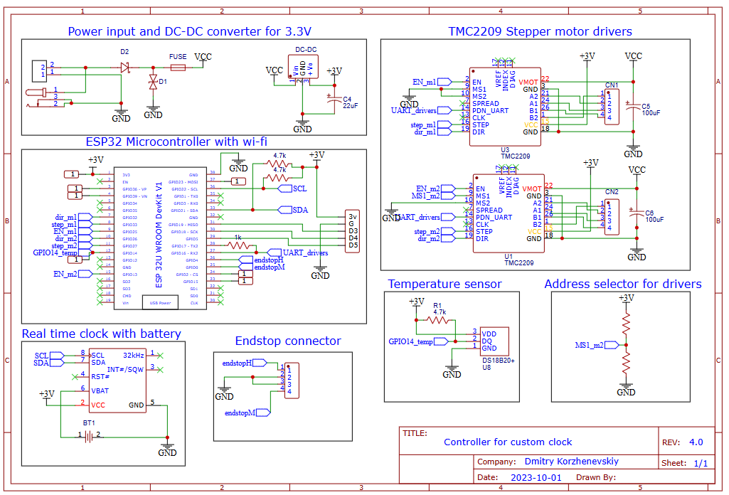
The first task is to choose the motor drivers. Thanks to the popularity of 3d printers multitude of motor drivers exist that could be used for this project.
I chose TMC2209 because of its silent operation and the ability to soft break without any significant power consumption. The silent operation is achieved by microstepping (the technology that splits steps of a stepper motor in a large number of substeps to make waveform more sine-looking than square-looking). I have two of those.
The machine is powered by 12V power supply. The average power consumption is less than 2W. When the motors turn the consumption rises to 5-10W. When motors are not moving the consumption is less than 1W.
The operation is completely silent. This was important design consideration since this clock must be placed at the office or at home and not act as a distraction when in moves.
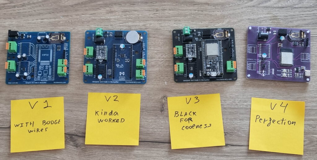
The PCB was designed to house the ESP32, DS3231 , two TMC2209 and the power management.
The PCB incorporates the temperature sensor situated near the motor driver as a overheating precaution. Later I discovered that this is not necessary since the motor driver always stays cold even without radiator attached. TMC2209 is incredibly efficient.
It took me 4 iterations to get rid of all mistakes and add all the needed features.
Hardware (mechanics)
Turn the drum, coil the rope, how hard can it be!? I though at the beginning.
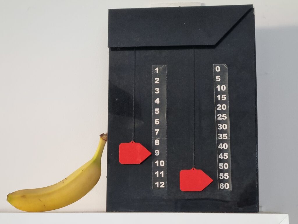
There are two ropes that attach the indicator. Why two? Of course only one can be used to attach a moving thing, but when only one is used there is no rotational stability. Here is the photo of the old version that I made in 2018. It has one string for the indicator. In order for it not to spin it is positioned against the wall and it slides up and down. It works fine but this method is not suitable for large wall installation.
For 2 string I need 2 coil. One solution is to have 2 motors with 1 coil each, or one motor that drives 2 coils with gears.
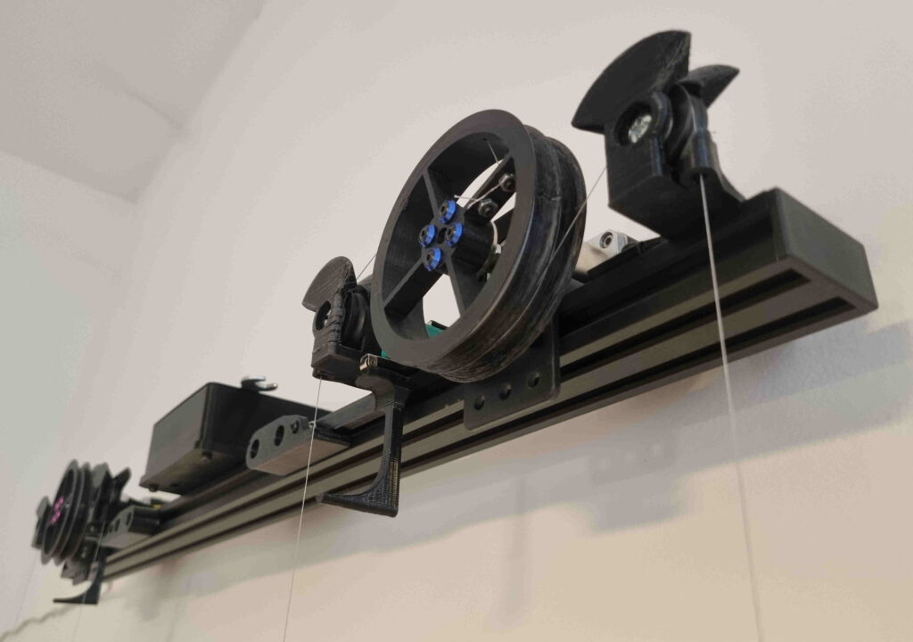
I made it simpler by mounting one double coil on one motor. Then 2 roller wheels are used to direct the string down at the right distance between each other.
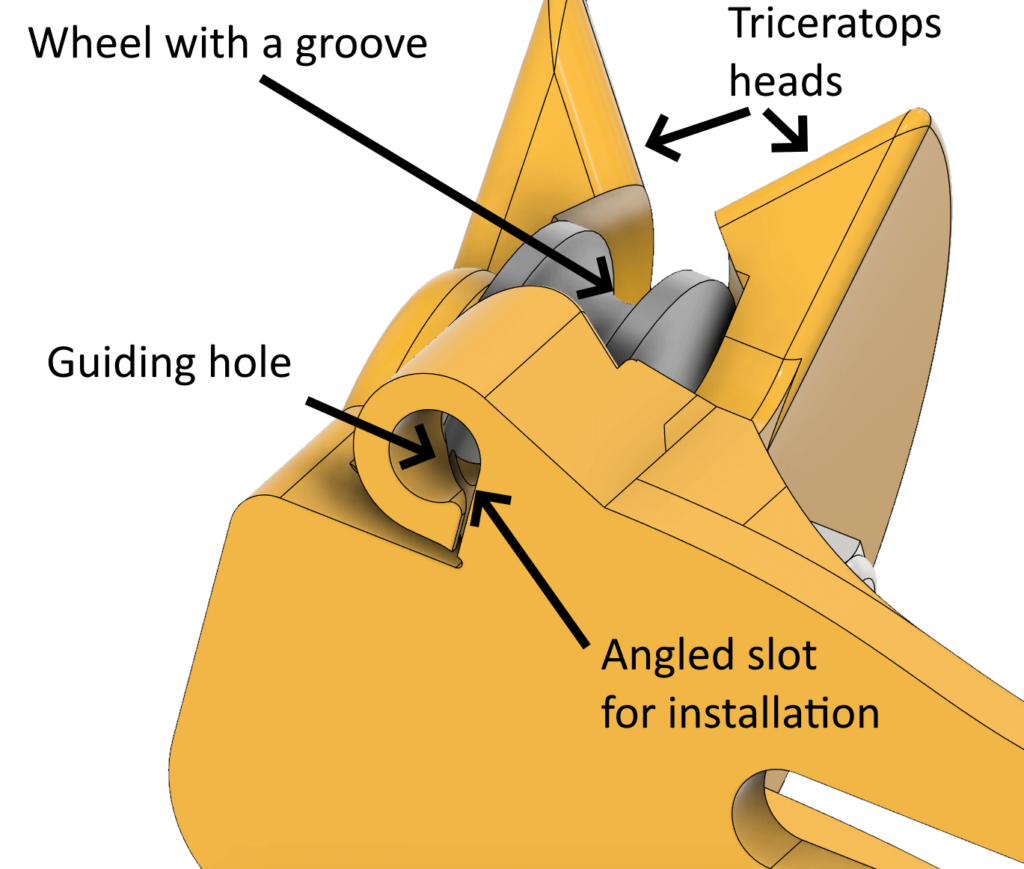
Notice the parts on the sides that look like the head of Triceratops.

The purpose of this part is to redirect the cable from the winding coil down to the indicator. Just a simple wheel on a bearing can be used for that. But this way we have a problem. What if someone touches the indicators (wine bottles)? What if the whole machine is disturbed? The cable will fall from the redirect wheels and the indicator will hang on the coiling drum.
The triceratops heads acts as a wire guide. In the event of wire lifting or coming out of alignment, it will naturally fall back inside the grooves of the wheel. After passing the wheel the cable is passed through the hole to keep in from swinging side to side to further improve the stability. The hole has a vertical inclined slot so the wire can be pushed through without the disassembly and without the need to disconnect the bottle.
Coiling challenge
Biggest challenge in the mechanics department of the this project for me was the coiling.
The wire is very thin but it still has some dimension. The calculation of the distance needed to be traveled is based on the fact that diameter of the coil do not change. Computer uses simple equation to calculate the rotation angle. Where r is a diameter of the coil.

When the wire is coiled it is stacked one on top of the other in a pile inside the coil thus increasing its diameter. After several turns the diameter becomes slightly larger and the indicator moves more that it should.
If both coils would deviate the same way that this would not be a problem, it could be easily be fixed with a calibration in the software. But of course in is not the same. The coiling behavior is random. One time they stack one time wire lies near itself. Its a nightmare!
But why it is a problem? It is visually unpleasant when the indicator changes its angle. If one coil starts to increase its speed even by 1% and another does not the indicator will be parallel to the ground at the lowest point and slightly not parallel when it is at highest point. Not much, but enough to be noticeable .
I started to experiment with the level to understand what causing this behavior.
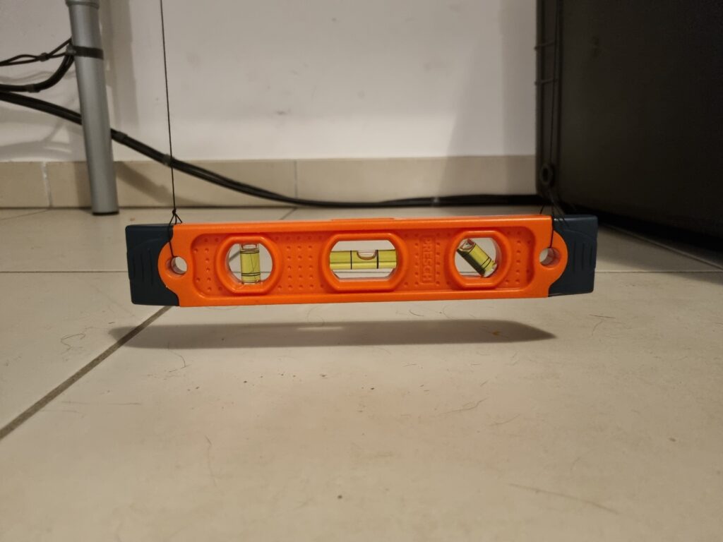
The goal was to make sure that it keeps level when fully up and fully down.
First I tried different drums geometries. I tried round grooves inside the wheel, elliptical grooves, flat grooves, different wall heights and angles.
Eventually I realized I must use flat bottom which is relatively wide and position the redirect wheel so it guides the wire right in the center of the coiling trench.
Then I experimented with different strings. I used nylon string – it was the worst for that job. It is too thick, is stacks on top of itself and does not want to slide to the trench.
I tried fishing line. It worked much better because it is thinner and smoother. It slides on the side when in lays on top of itself.
But the fishing line evoked another problem. It stretches. Not only it just elongates under load it also very slowly elongates over time when the load is applied constantly. This is totally unacceptable because if the machine is calibrated for a certain length and 1 month later the string became longer by 5% the indicated time will be off.
The best choice for that task is probably thin kevlar cord or dyneema cord since they a very static. I settled on a fishing line made out of polyethylene braided lines. It is surprisingly strong for it tiny width. It has no noticeable stretch under load. It can withstand the loads of 10 kg having the diameter of 0.20mm! Incredible!
The bottles were on that wire for 10 months without any noticeable stretching.
If however wires do stretch then there is a way to recalibrate the device without the need to update the firmware.
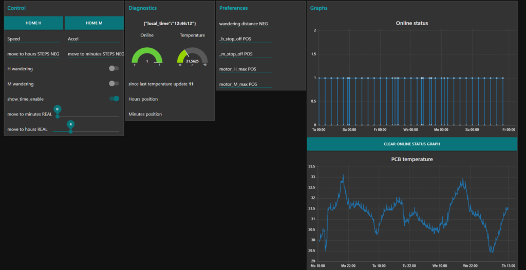
If the clock has internet connection the MQTT protocol can be used to enter all of the calibration values and for debugging.
Here is how online dashboard looks like. From here I can move the indicators manually, tweak the distances, change the speed and acceleration of the motors, monitor temperature.
It is made using Node-red with the plugin Node-red-dashboard.
Thanks for your attention.
If you have any questions regarding this project or any other of my projects don’t hesitate to send a message to
dmitrykorzhenevskiy@gmail.com
Best of luck
Dmitry

